Solved 3. complete the timing diagram for the equality Detector circuit diagram. Equality detector circuit diagram
Equality Detector Circuit Diagram
Equality detector
Detection circuit. schematic diagram of the electrical circuit
Equality detector circuit diagramEquality detector The diagram of equalization circuit. a schematic diagram and b printEquivalent circuit of the detector and readout electronics..
A proof of the circuit identity presented in fig. 13. the firstA) using an equivalent circuit diagram, derive the How to show equality in a presentation [concept visualization]Phase-detector under sensor circuits -13567- : next.gr.
![The logic circuit of the figure is aa)Half adderb)XORc)Equality](https://i2.wp.com/edurev.gumlet.io/ApplicationImages/Temp/9105db41-e86a-46be-a9de-9b00c6012902_lg.jpg)
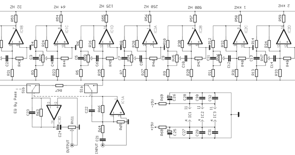
Passive equalizer circuit diagram
Equality detector circuit diagramThe detector equivalent circuit diagram [color figure can be viewed at Electrical – 3-bit equality detector with sequential circuit tThe logic circuit of the figure is aa)half adderb)xorc)equality.
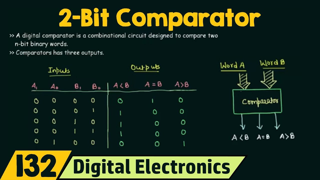
Phase detector circuit diagram electronic circuit wiring diagram pngEquality detector circuit diagram Equality pm visualization infodiagramSolved you need design an 8-bit equality detector. a fellow.
![PPT - Equality Detector PowerPoint Presentation, free download - ID:2951083](https://i2.wp.com/image1.slideserve.com/2951083/slide7-l.jpg)
Solved you need to design a 10-bit equality detector. a
6 band equalizer circuit diagram4 band equalizer circuit diagram Transistor equalizer circuit diagramEquivalent circuit of the balanced detector..
Equalizer passive pedalDetector's equivalent circuit. Detector circuit diagram.Schematic of the detector and modeled circuit. a experiment setup of.
![A proof of the circuit identity presented in Fig. 13. The first](https://i2.wp.com/www.researchgate.net/profile/Michal-Hajdusek/publication/276464772/figure/fig15/AS:289281714212875@1445981543578/A-proof-of-the-circuit-identity-presented-in-Fig-13-The-first-equality-is-by-Eq-A1.png)
Detector circuit. (a) the principle diagram of the detector circuit
The circuit shown in the given figure represents a/an:a)decoderbSchematic diagram of the detector circuit. .
.
![Equality Detector Circuit Diagram](https://i.ytimg.com/vi/BhUUmbz76P0/maxresdefault.jpg)
![How to Show Equality in a Presentation [concept visualization] - Blog](https://i2.wp.com/blog.infodiagram.com/wp-content/uploads/2020/08/Screen-Shot-2020-08-18-at-8.49.23-AM-1024x648.png)
![Electrical – 3-bit equality detector with sequential circuit T](https://i2.wp.com/i.stack.imgur.com/fmo1v.jpg)
![4 Band Equalizer Circuit Diagram](https://1.bp.blogspot.com/-RIkNrLc9qL4/TnJB3FvA-eI/AAAAAAAAAjc/TiKuCmxTzSs/w1200-h630-p-k-no-nu/10%2BBand%2BGraphic%2BEqualizer%2BCircuit.gif)
![Schematic of the detector and modeled circuit. a Experiment setup of](https://i2.wp.com/www.researchgate.net/profile/Yasith-Nanayakkara/publication/51682435/figure/download/fig1/AS:305779543429120@1449914932755/Schematic-of-the-detector-and-modeled-circuit-a-Experiment-setup-of-the-detector-b.png)
![Phase-detector under Sensor Circuits -13567- : Next.gr](https://i2.wp.com/www.next.gr/uploads/135-10060.png)
![Schematic diagram of the detector circuit. | Download Scientific Diagram](https://i2.wp.com/www.researchgate.net/profile/Shoaib-Usman/publication/3139675/figure/fig1/AS:349406533570560@1460316417010/Schematic-diagram-of-the-detector-circuit.png)
![Detector circuit diagram. | Download Scientific Diagram](https://i2.wp.com/www.researchgate.net/profile/Tadeusz-Wibig-2/publication/353118393/figure/fig2/AS:1043548946329605@1625812865901/Detector-circuit-diagram_Q320.jpg)
![6 Band Equalizer Circuit Diagram](https://i2.wp.com/circuitscheme.com/wp-content/uploads/2009/02/2x10-band-graphic-equalizer-schematic-1024x451.jpg)